How to quickly call CAD frames into SolidWorks drawings
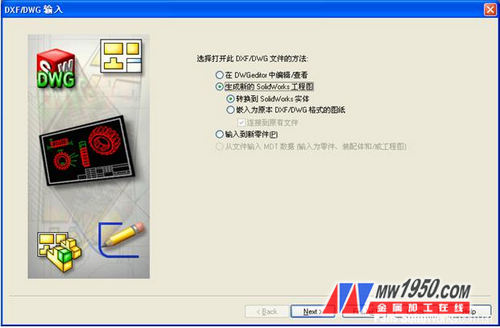
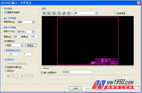
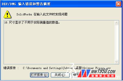
At present, many companies' engineering drawings have their own unique CAD frames. If you redraw these frames in SolidWorks drawings, it will take time to complete. How to realize the quick call of CAD frames to SolidWorks drawings It is the issue that everyone cares about. Since the frames are all present in the existing DWG format drawings, you can open them with the 2D design tool DWGeditor that comes with SolidWorks. The purpose is to measure the width and height of the frame, as shown in Figure 1. (Figure 1) After getting the data, open the CAD document directly through SolidWorks, and pop up the “DXF/DWG Input†dialog box. Here you can choose the method to open this DXF/DWG file. We need SolidWorks drawing, so choose the corresponding option as shown in Figure 2. (Figure II) Click “Next†to switch to the “DXF/DWG Input---Engineering Layer Mapping†dialog box. Because CAD documents mostly have multiple layers, select the layers belonging to the frame here, as shown in Figure 3. Show. (Figure 3) Click "Next" to switch to the "DXF/DWG Input---File Settings" dialog box. Here is the focus of the CAD frame call: 1: "Font attribute" is checked by default to ensure that the font width is consistent with the entire drawing scale. 2: The “Input File Properties†is selected in the unit of the width and height of the previous measurement frame. 3: Select "User Defined" in the paper size option of "Output File Properties", and then corresponding the frame width and height data. Fill it in. 4: The Drawing Drawing Scale is set to 1:1. 5: The Geometry Positioning selection is centered in the drawing. After completion, as shown in Figure 4. (Figure 4) After clicking "Finish", if the prompt shown in Figure 5 appears, you can skip by pressing "Close". (Figure 5) Next you can see that the CAD frame has been automatically added to the SolidWorks drawing, as shown in Figure 6. (Figure 6) However, at this time, the frame has not really become the SolidWorks drawing frame, so you need to cut the entire frame first, then enter the "Edit Drawing Format" state, then paste it up, place the position and exit the "Edit Drawing Format" state. The last step is to save the drawing as a "drawing template" format, as shown in Figure 7. (Figure 7) After saving, the quick conversion operation of the CAD frame is officially completed, and the desired frame can be obtained when the new drawing is created. Fiber Optics In Concrete Floor,Fiber Optic Floor Lamp,Deck And Patio Light,Fibre Optic Floor Lamp Jiangxi Daishing POF Co.,Ltd , https://www.jxopticfibrelight.com


These amazing fiber optic lighting comprise of inconspicuous miniature acrylic heads that are almost invisible when not in use. Come the evening you can switch on these deck and patio light and watch heads turn.
The fiber optic floor lamp light are also ideal for creating magical star effects in the floor of children`s bedrooms or play areas. The effect from these deck lighting kits is truly stunning, especially when used with a twinkle effect.
Typically installed in: wooden floors, wooden decking, paving, pathways, interior and exterior steps and stages. Tails of these deck lighting kits can be installed in cement, between paving slabs, stones or even in the grout between tiles.