The application of PLC in the numerical control transformation of lathe (2)
The designed lathe operation is: starting point total stop, Z, X direction fast forward, work advance, fast rewind; tool holder positive and negative; manual, automatic, single step, thread conversion. Therefore, the input requires 14 points. According to Figure 1, the output needs 9 points. The I/O connection diagram is shown in Figure 2 (using Mitsubishi F1S-30MT) as an example. 4 driver (ladder) design 4.1 General program structure design The selection of manual, automatic, single-step, and threaded programs is implemented using jump instructions. Figure 3 is a block diagram of the overall program structure. If X12 (X13, X14, X15 is disconnected) is closed, it is normally closed and the manual program is executed. If X12 is disconnected, X13 is all up, the program skips the manual program, and the pointer goes to P0 to execute the automatic program. 4.2 Manual program ladder design The manual program and the automatic program need to be designed according to the specific parts. Here, only the Z-direction fast forward, work advance, and fast reverse action will be described as an example. Its ladder diagram is shown in Figure 4. In the manual program state, press X0, Y1 to turn on, and prepare for starting. Press X2 and the auxiliary relay M0 is turned on. Through the T63 timing and Y2 contact combination, a pulse signal with a frequency of 103/2i is generated (i is the timing time, set according to need, the unit is ms), and the Z direction is fast forwarded. When X3 is pressed (M0 is turned off), M1 is turned on, and M1 is combined with timer T32 to make Y2 generate a pulse of frequency 103/2j (j>i), which is output by Y2 to realize the work advance. When X4 is pressed, M0 and Y3 are turned on at the same time, and the motor is quickly reversed to realize fast rewind. Due to space limitations, other program ladder diagrams are omitted. [2] Previous page next page
Dosing Pump Characteristic :
1 Clean and pollution-free: fluid only passes through and touches the Peristaltic Pump hose.
Dosing Pump,Laboratory Peristaltic Pump,Metering Pump,Peristaltic Dosing Pump Baoding Chuangrui Precision Pump Co., Ltd. , https://www.chuangruipump.com
3 PLC input and output (I/O) points are determined 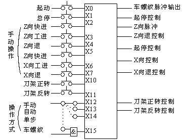
Figure 2 I / O connection diagram 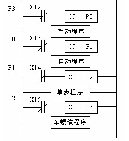
Figure 3 overall block diagram 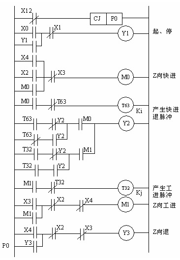
Figure 4 Z-direction manual program ladder diagram
3. Low shear force: It is an ideal tool for conveying shear-sensitive and corrosive fluids.
4. Corrosion resistance: it can transport various fluids, such as organic solvents and corrosive liquids.
5. Idling and dry operation: air or gas-liquid-solid three-phase mixed transportation can also be transported.
6. Possess self-priming ability: self-priming, no need to fill the pump, no need to empty.
7. It has the function of a shut-off valve, does not siphon, has no seals, and has the functions of a shut-off valve and a check valve.
8. Two-way conveying function: reverse pumping and back-suction functions can be realized by changing the direction of the pump runner.
9. Simple maintenance: only need to replace the peristaltic pump hose, no valve and seal replacement.